


 0
0
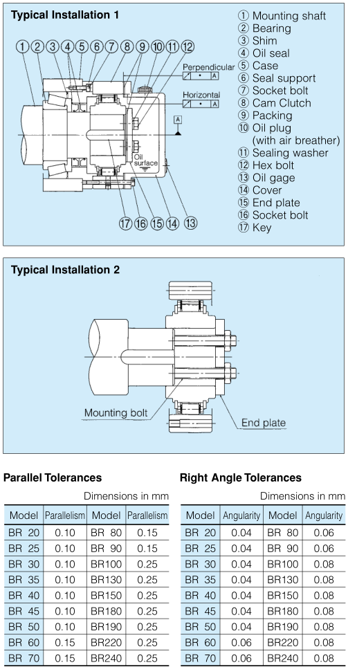
■ MODELS BR20 TO BR240
For Backstop and Overrunning Applications

Dimension (Open Type)
Model | Bore Size | A | B | C | D | E | F | Mounting Holes | Pulloff Holes | H min | I | J | K | L | M max | |||
Dia. (H7) | Keyway | Chamfer O | PCD | No.-Dia. | No.-Size | |||||||||||||
G | Q-R | S-T | ||||||||||||||||
BR 20 | 20 | 6x2.8 | 0.5 | 35 | 35 | 90 | 66 | 40.7 | 40.7 | 78 | 6- 6.6 | 2-M 6 | 53 | 0 | 0 | 5 | 5 | 4.0 |
BR 25 | 25 | 8x3.3 | 0.5 | 35 | 35 | 95 | 70 | 44.7 | 44.7 | 82 | 6- 6.6 | 2-M 6 | 58 | 0 | 0 | 5 | 5 | 4.0 |
BR 30 | 30 | 8x3.3 | 1.0 | 35 | 35 | 100 | 75 | 49.7 | 49.7 | 87 | 6- 6.6 | 2-M 6 | 64 | 0 | 0 | 5 | 5 | 4.0 |
BR 35 | 35 | 10x3.3 | 1.0 | 35 | 35 | 110 | 80 | 54.7 | 54.7 | 96 | 8- 6.6 | 2-M 6 | 70 | 0 | 0 | 5 | 5 | 4.0 |
BR 40 | 40 | 12x3.3 | 1.0 | 35 | 35 | 125 | 90 | 64.7 | 64.7 | 108 | 8- 9.0 | 2-M 8 | 81 | 0 | 0 | 5 | 5 | 4.0 |
BR 45 | 45 | 14x3.8 | 1.0 | 35 | 35 | 130 | 95 | 69.7 | 69.7 | 112 | 8- 9.0 | 2-M 8 | 86 | 0 | 0 | 5 | 5 | 4.0 |
BR 50 | 50 | 14x3.8 | 1.0 | 40 | 40 | 150 | 110 | 84.7 | 84.7 | 132 | 8- 9.0 | 2-M 8 | 103 | 0 | 0 | 7.5 | 7.5 | 6.5 |
BR 60 | 60 | 18x4.4 | 1.5 | 60 | 50 | 175 | 125 | 80 | 80 | 155 | 8-11.0 | 2-M10 | 110 | 5 | 5 | 7 | 7 | 6.0 |
BR 70 | 70 | 20x4.9 | 1.5 | 60 | 50 | 190 | 140 | 95 | 95 | 165 | 12-11.0 | 2-M10 | 125 | 5 | 5 | 7 | 7 | 6.0 |
BR 80 | 80 | 22x5.4 | 1.5 | 70 | 60 | 210 | 160 | 115 | 115 | 185 | 12-11.0 | 2-M10 | 148 | 5 | 5 | 12 | 12 | 11.0 |
BR 90 | 90 | 25 x5.4 | 1.5 | 80 | 70 | 230 | 180 | 135 | 135 | 206 | 12-13.5 | 2-M12 | 170 | 5 | 5 | 17 | 17 | 16.0 |
BR100 | 100 | 28x6.4 | 1.5 | 90 | 80 | 270 | 210 | 143 | 143 | 240 | 12-17.5 | 2-M16 | 180 | 5 | 5 | 13.7 | 13.7 | 12.0 |
BR130 | 130 | 32 x7.4 | 2.0 | 90 | 80 | 310 | 240 | 173 | 173 | 278 | 12-17.5 | 2-M16 | 210 | 5 | 5 | 13.7 | 13.7 | 12.0 |
BR150 | 150 | 36x8.4 | 2.0 | 90 | 80 | 400 | 310 | 243 | 243 | 360 | 12-17.5 | 2-M16 | 280 | 5 | 5 | 13.7 | 13.7 | 12.0 |
BR180 | 180 | 45x10.4 | 2.0 | 105 | 80 | 400 | 310 | 290 | 270 | 360 | 12-17.5 | 2-M16 | 280 | 5 | 20 | 11.5 | 15.9 | 14.0 |
BR190 | 190 | 45x10.4 | 2.0 | 105 | 80 | 420 | 330 | 310 | 286 | 380 | 16-17.5 | 2-M16 | 300 | 5 | 20 | 12.5 | 8.9 | 7.5 |
BR220 | 220 | 50x11.4 | 2.0 | 105 | 80 | 460 | 360 | 340 | 320 | 410 | 18-17.5 | 2-M16 | 330 | 5 | 20 | 12.5 | 10.9 | 9.0 |
BR240 | 240 | 56x12.4 | 2.0 | 105 | 80 | 490 | 390 | 370 | 350 | 440 | 18-17.5 | 2-M16 | 360 | 5 | 20 | 12.5 | 10.9 | 9.0 |
Model | Chamfer | U | Oil Plug Position/Dia. | Weight | Inertial Moment | |||
N | P | V | W | X×PT-Y | ||||
BR 20 | 1.5 | 1.5 | 30.0 | 17.5 | − | 4 × PT-1/16 | 1.3 | 2.25 × 10⁻⁴ |
BR 25 | 1.5 | 1.5 | 30.0 | 17.5 | − | 4 × PT-1/16 | 1.4 | 3.28 × 10⁻⁴ |
BR 30 | 1.5 | 1.5 | 30.0 | 17.5 | − | 4 × PT-1/16 | 1.5 | 4.44 × 10⁻⁴ |
BR 35 | 1.5 | 1.5 | 22.5 | 17.5 | − | 4 × PT-1/8 | 1.9 | 5.65 × 10⁻⁴ |
BR 40 | 1.5 | 1.5 | 22.5 | 17.5 | − | 4 × PT-1/8 | 2.4 | 1.01 × 10⁻³ |
BR 45 | 1.5 | 1.5 | 22.5 | 17.5 | − | 4 × PT-1/8 | 2.6 | 1.22 × 10⁻³ |
BR 50 | 2.5 | 2.0 | 22.5 | 20 | − | 4 × PT-1/8 | 4.1 | 2.64 × 10⁻³ |
BR 60 | 3.5 | 2.0 | 22.5 | 25 | − | 4 × PT-1/8 | 7.3 | 3.73 × 10⁻³ |
BR 70 | 3.5 | 2.0 | 15.0 | 25 | − | 4 × PT-1/8 | 8.1 | 6.65 × 10⁻³ |
BR 80 | 3.5 | 2.0 | 15.0 | 14 | 32 | 4 × PT-1/8 | 12.0 | 1.77 × 10⁻² |
BR 90 | 3.5 | 2.0 | 15.0 | 19 | 32 | 4 × PT-1/8 | 16.0 | 3.16 × 10⁻² |
BR100 | 4.5 | 2.0 | 15.0 | 20 | 40 | 4 × PT-1/4 | 23.0 | 6.31 × 10⁻² |
BR130 | 4.5 | 2.0 | 15.0 | 20 | 40 | 4 × PT-1/4 | 31.0 | 0.109 |
BR150 | 4.5 | 3.0 | 15.0 | 20 | 40 | 4 × PT-1/4 | 58.0 | 0.365 |
BR180 | 4.5 | 3.0 | 15.0 | 20 | 40 | 4 × PT-1/4 | 60.0 | 0.435 |
BR190 | 4.5 | 3.0 | 11.25 | 20 | 40 | 4 × PT-1/4 | 65.0 | 0.563 |
BR220 | 4.5 | 3.0 | 10.0 | 20 | 40 | 4 × PT-1/4 | 76.0 | 0.789 |
BR240 | 4.5 | 3.0 | 10.0 | 20 | 40 | 4 × PT-1/4 | 84.0 | 1.05 |
Notes:
1. Package type Cam Clutches are all made to order. To order, please refer to the dimension diagram. Please inform us if the Cam Clutch is to be used in a vertical application, and if the operating environment temperature will be less than –5°C or more than +40°C.
2. There are cases when the free running rotation speed of the inner race will be limited when package type Cam Clutches are installed horizontally,
3. If your application calls for a clutch engagement speed or inner race free running speed not listed in this catalog,please contact TSUBAKI .
Dimensions (Package Type)
Model | Bore Size(H7) | Keyway | A | B | C(h7) | D | PCDE | F-G | weight(kg) |
BR 20P | 20 | 6X2.8 | 87 | 79 | 94 | 35 | 78 | 6-M 6×12 | 3.4 |
BR 25P | 25 | 8X3.3 | 89 | 81 | 98 | 40 | 82 | 6-M 6×12 | 3.8 |
BR 30P | 30 | 8X3.3 | 94 | 85 | 103 | 45 | 87 | 6-M 6×12 | 4.3 |
BR 35P | 35 | 10X3.3 | 94 | 85 | 112 | 50 | 96 | 8-M 6×12 | 5.1 |
BR 40P | 40 | 12X3.3 | 100 | 91 | 130 | 55 | 108 | 8-M 8×16 | 7.5 |
BR 45P | 45 | 14X3.8 | 100 | 91 | 135 | 60 | 112 | 8-M 8×16 | 7.9 |
BR 50P | 50 | 14X3.8 | 107 | 98 | 152 | 70 | 132 | 8-M 8×16 | 10.9 |
BR 60P | 60 | 18X4.4 | 122 | 112 | 180 | 80 | 155 | 8-M10×20 | 17.5 |
BR 70P | 70 | 20X4.9 | 128 | 118 | 190 | 90 | 165 | 12-M10×20 | 19.5 |
BR 80P | 80 | 22X5.4 | 148 | 134 | 210 | 105 | 185 | 12-M10×20 | 27 |
BR 90P | 90 | 25X5.4 | 152 | 138 | 235 | 120 | 206 | 12-M12×24 | 35 |
BR100P | 100 | 28X6.4 | 186 | 172 | 275 | 140 | 240 | 12-M16×32 | 60 |
BR130P | 130 | 32X7.4 | 208 | 188 | 314 | 160 | 278 | 12-M16×32 | 80 |
BR150P | 150 | 36X8.4 | 226 | 204 | 400 | 200 | 360 | 12-M16×32 | 151 |
BR180P | 180 | 45X10.4 | 240 | 218 | 400 | 220 | 360 | 12-M16×32 | 169 |
BR190P | 190 | 45X10.4 | 250 | 242 | 420 | 240 | 380 | 16-M16×32 | 193 |
BR220P | 220 | 50X11.4 | 250 | 242 | 460 | 260 | 410 | 18-M16×32 | 220 |
BR240P | 240 | 56X12.4 | 260 | 252 | 490 | 280 | 440 | 18-M16×32 | 267 |
Note: Above drawing is an example. Request a certified drawing when ordering, as specifications vary with each model.
Capacities (Open Type) ModelTorque Capacity (N·m)Inner Race Overrunning SpeedMax. Engagement(r/min)Min.(r/min)Max. (r/min)BR 203068803,600350BR 253848803,600350BR 306078803,600350BR 356867803,600300BR 409807203,600300BR 451,0786703,600280BR 501,7156103,600240BR 603,4794903,600200BR 704,7354803,600200BR 806,5174503,600190BR 908,5264203,000180BR10014,2104602,700180BR13020,3844202,400180BR15033,9083701,300160BR18033,9083703,500160BR19041,1603403,000140BR22051,0583303,000140BR24062,0343103,000130 | Capacities (Package Type) ModelTorque Capacity (N·m)Inner Race Overrunning SpeedMax. Engagement(r/min)Min.(r/min)Max. (r/min)BR 20P3068803,600350BR 25P3848803,600350BR 30P6078803,600350BR 35P6867803,600300BR 40P9807203,600300BR 45P1,0786703,600280BR 50P1,7156103,600240BR 60P3,4794903,600200BR 70P4,7354803,600200BR 80P6,5174503,600190BR 90P8,5264203,000180BR100P14,2104602,500180BR130P20,3844202,200180BR150P33,9083701,300160BR180P33,9083701,800160BR190P41,1603401,800140BR220P51,0583301,800140BR240P62,0343101,800130 |
■ USING THE BR SERIES OPEN TYPE CAM CLUTCH
While the Cam Clutch can be disassembled by the user, reassembly may prove difficult. We recommend that you
install the Cam Clutch as delivered.
|  |
■ USING THE BR SERIES PACKAGE TYPE CAM CLUTCH
Similar to previous types, the package type Cam Clutch is designed into a ball bearing cassette that makes
installation with a torque arm and/or coupling fast and easy. The package type Cam Clutch is grease lubricated.
Installation and Usage |  |

On the other hand denoune with righteou indignat and dislike menar so beguiled demoralized echarms of pleasure of the moment so blinded by desire that systems.
E-mail: ellen@chinasuma.com
Mobile: 0086-18068536660
Tel: 0086-519-85858018
Fax: 0086-519 85858018
WhatsApp: +86-18068536660
Add: Liudao Industrial Park, YaoguanTown, Wujin District , Changzhou City , Jiangsu Province, China , 213102


