


Integrated Sprag Freewheels FXM … NX and FXM … MX
Integrated Freewheels FXM are sprag free - wheels without bearing support and with sprag
lift-off X.
lift-off X.

 0
0

Freewheel Size | Type | Theoretical nominal torque 0A Nm | 0,1A Nm | 0,2A Nm | Nominal torque at existing run out (T.I.R.) 0,3A Nm | 0,4A Nm | 0,5A Nm | Sprag lift-off at inner ring speed min-1 | Max. speed ring freewheels / | |
FXM | 31 - 17 | NX | 110 | 110 | 105 | 100 | 890 | 5 000 | ||
FXM | 38 - 17 | NX | 180 | 170 | 160 | 150 | 860 | 5 000 | ||
FXM | 46 - 25 | NX | 460 | 450 | 440 | 430 | 820 | 5 000 | ||
FXM | 51 - 25 | NX | 560 | 550 | 540 | 530 | 750 | 5 000 | ||
FXM | 56 - 25 | NX | 660 | 650 | 640 | 630 | 730 | 5 000 | ||
FXM | 61 - 19 | NX | 520 | 500 | 480 | 460 | 750 | 5 000 | ||
FXM | 66 - 25 | NX | 950 | 930 | 910 | 890 | 700 | 5 000 | ||
FXM | 76 - 25 | NX | 1 200 | 1 170 | 1 140 | 1 110 | 670 | 5 000 | ||
FXM | 86 - 25 | NX | 1 600 | 1 550 | 1 500 | 1 450 | 630 | 5 000 | ||
FXM | 101 - 25 | NX | 2 100 | 2 050 | 2 000 | 1 950 | 610 | 5 000 | ||
FXM | 85 - 40 | MX | 2 500 | 2 500 | 2 450 | 2 450 | 2 450 | 2 450 | 430 | 6 000 |
FXM | 100 - 40 | MX | 3 700 | 3 600 | 3 600 | 3 500 | 3 500 | 3 500 | 400 | 4 500 |
FXM | 120 - 50 | MX | 7 700 | 7 600 | 7 500 | 7 300 | 7 300 | 7 300 | 320 | 4 000 |
FXM | 140 - 50 | MX | 10 100 | 10 000 | 9 800 | 9 600 | 9 500 | 9 500 | 320 | 3 000 |
FXM | 170 - 63 | MX | 20 500 | 20 500 | 20 000 | 19 500 | 19 000 | 19 000 | 250 | 2 700 |
FXM | 200 - 63 | MX | 31 000 | 30 500 | 30 000 | 26 500 | 23 000 | 20 500 | 240 | 2 100 |
The maximum transmissible torque is 2 times the specified nominal torque. See page 14 for determination of selection torque.
The theoretical nominal torque applies only for ideal concentricity between the inner and outer ring. In practice, the concentricity is affected by the bearing play and centering errors of the neigh bour-
ing parts. Then the nominal torques specified in the table apply, whilst taking into consideration the existing run out (T.I.R.).
Higher speeds upon request.
Mounting
Integrated Freewheels FXM are without bearing support. Concentric alignment of inner and outer ring must be provided by the customer. The permissible run out (T.I.R.) must be ob s erved.
The Integrated Freewheel FXM is centered via For fitting to shaft ends, end covers can be supthe outer track F on the customer attachment plied upon request (refer to figure 67-3).
part and bolted to this (refer to figure 67-1). The tolerance of the pilot diameter of the attachment part must be ISO h6 or h7.
The tolerance of the shaft must be ISO h6 or j6.
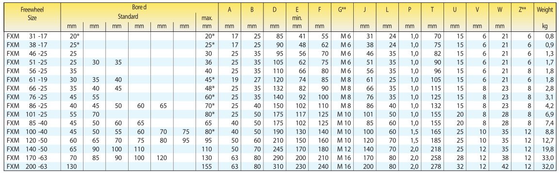
Keyway according to DIN 6885, page 1 • Tolerance of keyway width JS10.
* Keyway according to DIN 6885, page 3 • Tolerance of keyway width JS10.
** Z = Number of fastening holes for screws G on pitch circle T.
Lubrication | Example for ordering Freewheel size FXM 140 - 50, type with sprag lift-off X and 100 mm bore and end cover: • FXM 140 - 50 MX, d = 100 mm, with end cover |
Product display


On the other hand denoune with righteou indignat and dislike menar so beguiled demoralized echarms of pleasure of the moment so blinded by desire that systems.
E-mail: ellen@chinasuma.com
Mobile: 0086-18068536660
Tel: 0086-519-85858018
Fax: 0086-519 85858018
WhatsApp: +86-18068536660
Add: Liudao Industrial Park, YaoguanTown, Wujin District , Changzhou City , Jiangsu Province, China , 213102


